 EN

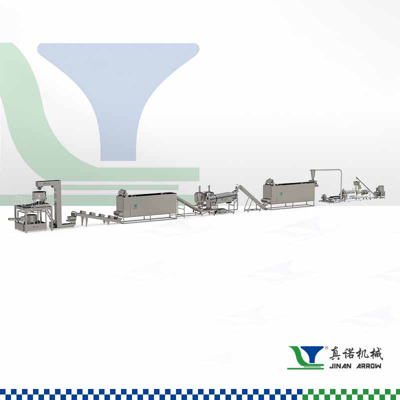
Core Unit Operations and Their Spatial Footprint
From grits cooking to flake toasting: area allocation per stage
The spatial layout of a corn flakes production line directly impacts throughput, food safety compliance, and operational flexibility. Cooking and preconditioning—including grits hydration and steam injection—account for 40–45% of total floor area. Table 1 outlines typical space allocation for a 500–700 kg/h line.
| Process Stage | Approx. Floor Area (m²) | Share of Total |
|---|---|---|
| Grits Cooking & Quenching | 50–70 | 22% |
| Tempering & Drying | 60–80 | 25% |
| Flaking & Roll Milling | 30–45 | 14% |
| Toasting & Final Drying | 40–55 | 17% |
| Cooling & Conveying Buffers | 25–40 | 12% |
| Control & Utility Access | 20–35 | 10% |
Drying and tempering zones dominate the footprint due to extended residence times—up to 3–4 hours—to ensure uniform moisture equilibration. Continuous flaking mills reduce footprint by 15% compared to batch roll mills, while high-temperature short-time (HTST) toasters cut dryer length by half versus traditional rotary dryers, freeing space for packaging integration. Steam-jacketed kettles and clean-in-place (CIP) infrastructure in the cooking area require an additional 10–15% spatial buffer for operator access and sanitation compliance. Planning must therefore include expansion allowances for each unit operation to support future capacity upgrades without disrupting workflow integrity.
Thermal and mechanical constraints: steam zones, cooling corridors, and expansion allowances
Corn flakes production generates intense thermal loads—particularly during cooking and toasting—that demand deliberate zoning. Steam injection vessels can raise ambient temperatures to 55°C, requiring dedicated steam zones with overhead clearance of at least 2.5 m for hoods and exhaust ducts, per EHEDG guidelines. Steam piping isolation corridors must provide a minimum 1.2 m width for safe access and maintenance.
Cooling corridors downstream of toasting—where flakes drop from ~220°C to <40°C—require linear, unobstructed paths. Standard ambient cooling tunnels extend 12–15 m, adding 25–30 m² to the layout. Mechanical expansion of heated stainless steel components is significant: a 10 m pipe may elongate by 2.5 cm. To accommodate this, flexible couplings and expansion loops are recommended every 8–10 m, consuming an extra 8–12% of the machine envelope. Ignoring these factors risks misalignment, seal failure, and contamination pathways—making thermal zoning foundational to long-term reliability.
Equipment Footprint and Installation Requirements for Corn Flakes Production Line Machinery
Key machinery dimensions: extruder, flake drum dryer, and rotary toaster
Core equipment dimensions drive overall line geometry. A twin-screw extruder—the starting point for grits cooking and forming—typically occupies 4 m × 1.5 m for medium-capacity lines (120–150 kg/h), scaling to over 6 m × 3.5 m at 500 kg/h. Downstream, the flake drum dryer reduces moisture from ~20% to 5%, requiring a drying chamber 6–8 m long and an overall footprint of ~8 m × 2 m. The rotary toaster adds another 5–7 m of linear space to achieve final color and crispness. As a result, a 150 kg/h system may span 39 m × 1.2 m, while a 500 kg/h configuration reaches up to 43 m × 3.5 m. These figures underscore how modest capacity increases disproportionately expand spatial requirements—making early equipment footprint analysis essential for facility planning.
Service access, clearance, and maintenance envelope standards
Operational clearances often double the effective footprint beyond static equipment dimensions. Industry best practice mandates a minimum 1.2 m perimeter walkway around each major unit for operator movement, and 1.5 m clearance in front of electrical panels and control cabinets to meet safety regulations. Overhead clearance must accommodate steam exhaust ducts and ventilation systems—requiring at least 2.5 m above the highest point of dryers or toasters. Maintenance envelopes must permit full component extraction: drum dryers, for example, need end-access doors with sufficient lateral room to remove the entire drum for resurfacing. Conveyors, dust extraction hoods, and metal detection stations also consume floor space; integrating them into service corridors—not as afterthoughts—prevents bottlenecks and minimizes downtime during cleaning or repairs.
Functional Zoning Strategy for Optimal Corn Flakes Production Line Layout
Raw material storage, production core, QC lab, and finished goods zones
Functional zoning transforms discrete machines into a cohesive, high-throughput system aligned with HACCP and lean 5S principles. Four distinct zones must be clearly separated: raw material storage, production core, quality control (QC) laboratory, and finished goods storage.
Raw material silos for grits and minor ingredients should be located upwind of processing to prevent steam and dust migration, typically occupying 10–15% of total floor space. The production core—spanning cooking, flaking, and toasting—requires strict linear flow from wet to dry zones, with equipment spacing exceeding 1.5 m to accommodate dust extraction hoods and maintenance access. A mid-line QC lab, positioned adjacent to the toaster exit, enables immediate moisture and color testing—preventing out-of-spec batches from entering packaging and reducing product loss by up to 3%, per food engineering benchmarks. Finished goods zones must be strictly segregated from raw material areas to eliminate cross-contact; integrated packaging material storage and conveyor networks should link palletizing and shrink-wrapping directly to the dispatch bay. This disciplined approach curtails non-value-added movement and strengthens food safety assurance.
Auxiliary Systems and Infrastructure Impact on Total Space Needs
Dust collection, metal detection, conveying networks, and packaging line footprints
Auxiliary systems account for a substantial—and often underestimated—portion of total space requirements, frequently rivaling that of primary processing equipment. Dust collection systems (cyclones, baghouses) demand dedicated mechanical zones with explosion venting and captive maintenance access; associated ductwork can increase building height by 15–20%. Metal detectors require several meters of straight conveyor upstream for reliable detection, plus dedicated space for rejection mechanisms and locked reject bins.
Conveying networks—including pneumatic lifts, inclined belt conveyors, and bucket elevators—must bridge multiple floor levels while avoiding dead legs and enabling CIP access; supporting walkways, platforms, and vertical chases all add to floor and overhead demands. Finally, the packaging line—from vertical form-fill-seal baggers to case packers and palletizers—can occupy up to 40% of total floor area in compact layouts. Underestimating these infrastructure needs inevitably creates bottlenecks that compromise throughput, food safety, and maintenance accessibility.
FAQ
What factors primarily affect the spatial layout of a corn flakes production line?
The spatial layout is influenced by throughput goals, food safety compliance, operational flexibility, and the dimensions and clearance requirements of core machinery such as extruders, drum dryers, and toasters.
Why do drying and tempering zones require a significant footprint?
Drying and tempering need extended residence times of up to 3–4 hours for uniform moisture equilibration, which necessitates larger floor areas.
What is the impact of auxiliary systems on total space requirements?
Auxiliary systems like dust collection, metal detection, and conveying networks can rival primary equipment in spatial demands. These systems often add height and horizontal space to the layout.
How can thermal loads be managed effectively in production zones?
Thermal loads can be managed using dedicated zones for steam systems, overhead clearance for hoods and ducts, flexible couplings to prevent thermal expansion issues, and well-planned cooling corridors.
Why is equipment footprint analysis critical in early planning?
Early footprint analysis ensures facility layouts can accommodate future capacity upgrades and meet regulatory standards without disrupting workflow integrity.
Table of Contents
- Core Unit Operations and Their Spatial Footprint
- Equipment Footprint and Installation Requirements for Corn Flakes Production Line Machinery
- Functional Zoning Strategy for Optimal Corn Flakes Production Line Layout
- Auxiliary Systems and Infrastructure Impact on Total Space Needs
-
FAQ
- What factors primarily affect the spatial layout of a corn flakes production line?
- Why do drying and tempering zones require a significant footprint?
- What is the impact of auxiliary systems on total space requirements?
- How can thermal loads be managed effectively in production zones?
- Why is equipment footprint analysis critical in early planning?